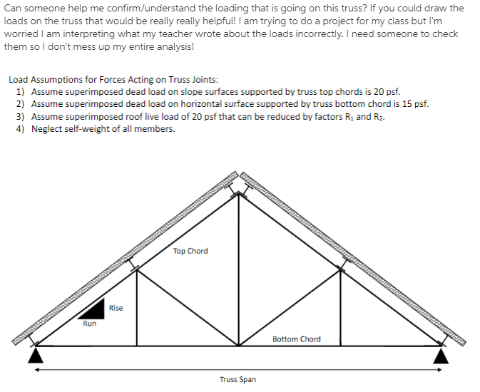
Finding Roof Loading On A Truss At Joints Chegg
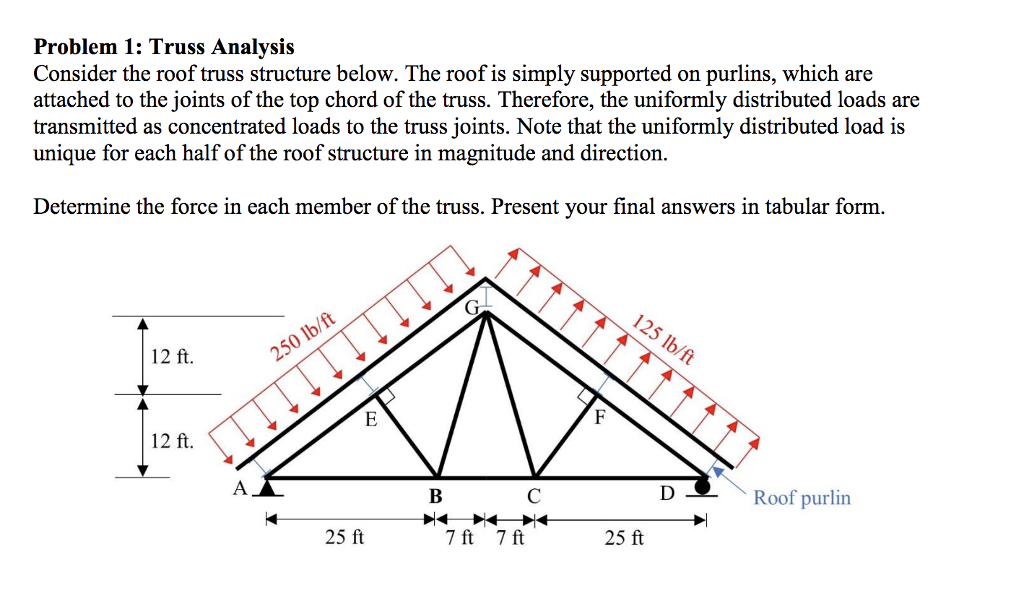
Solved Problem 1 Truss Analysis Consider The Roof Truss Chegg Com

Picture 1 Ideias Para Oficinas Arquitetura Pergola
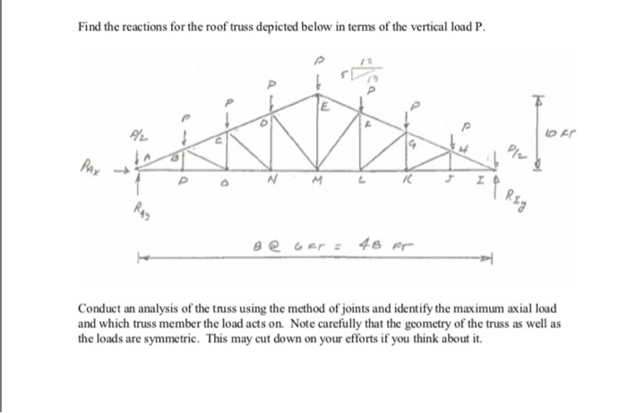
Solved Find The Reactions For The Roof Truss Depicted Bel Chegg Com
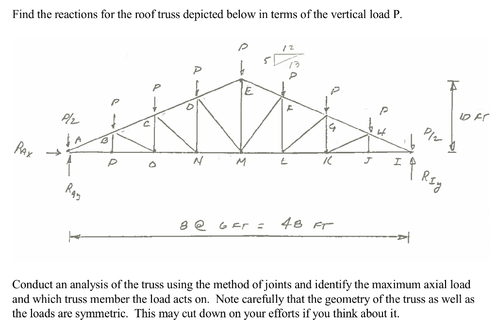
Solved Find The Reactions For The Roof Truss Depicted Bel Chegg Com
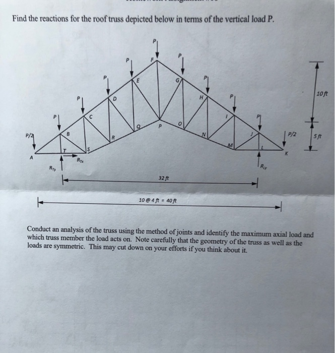
Solved Find The Reactions For The Roof Truss Depicted Bel Chegg Com
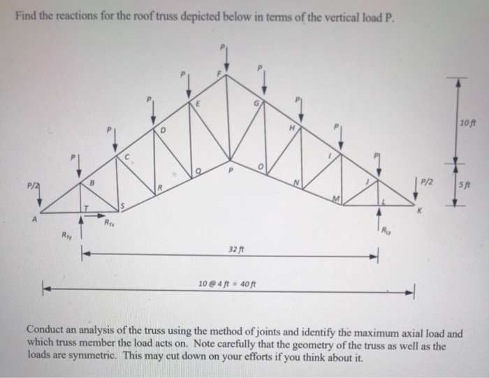
Solved Find The Reactions For The Roof Truss Depicted Bel Chegg Com
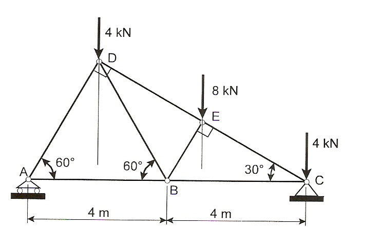
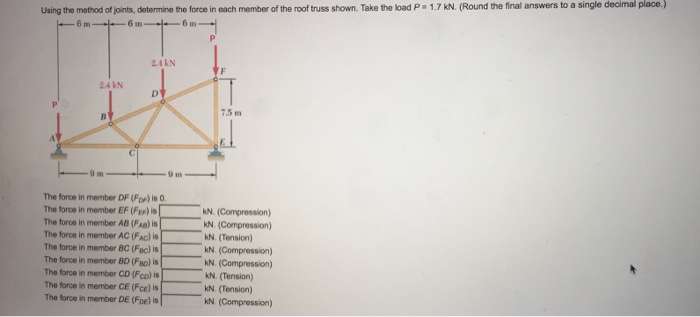
Use the method of joints for both numbers to determine the force in each member of the roof truss shown.
Finding roof loading on a truss at joints chegg.

Model Is Of Tension Trusses That Would Be Covered By A Hard Material Such As Ceramic Civil Engineering Construction Civil Engineering Civil Engineering Design
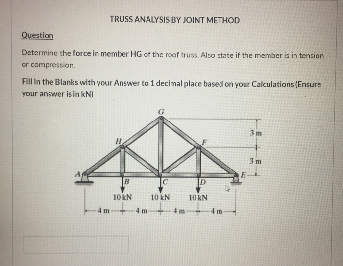
Solved Truss Analysis By Joint Method Question Determine Chegg Com
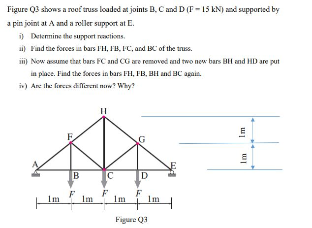
Solved Figure Q3 Shows A Roof Truss Loaded At Joints B C Chegg Com
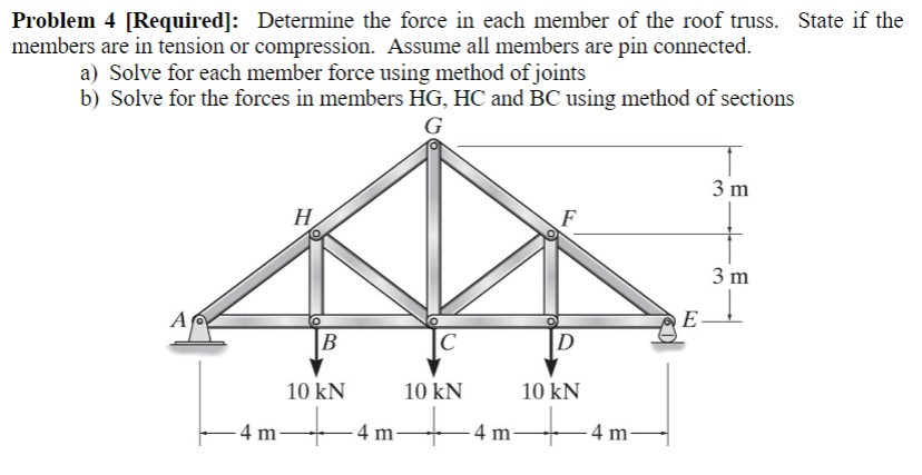
Solved Problem 4 Required Determine The Force In Each Chegg Com
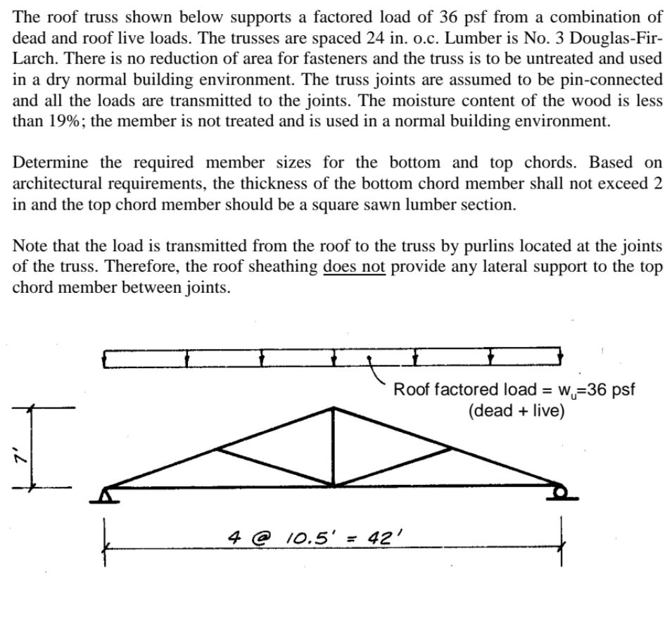
Solved The Roof Truss Shown Below Supports A Factored Loa Chegg Com
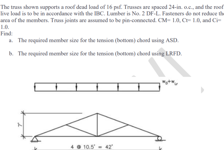
The Truss Shown Supports A Roof Dead Load Of 16 Ps Chegg Com
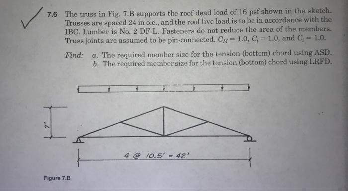
The Truss In Fig 7 B Supports The Roof Dead Load Chegg Com
Solved Determine The Force In Each Member Of The Roof Truss Sh Chegg Com
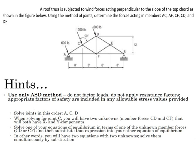
Solved A Roof Truss Is Subjected To Wind Forces Acting Pe Chegg Com
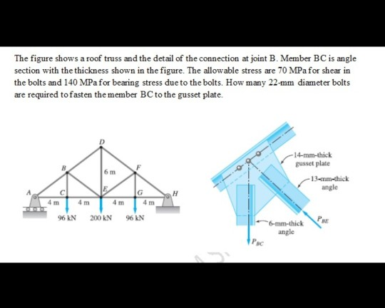
Solved The Figure Shows A Roof Truss And The Detail Of Th Chegg Com
Wcw2nignkqpcnm
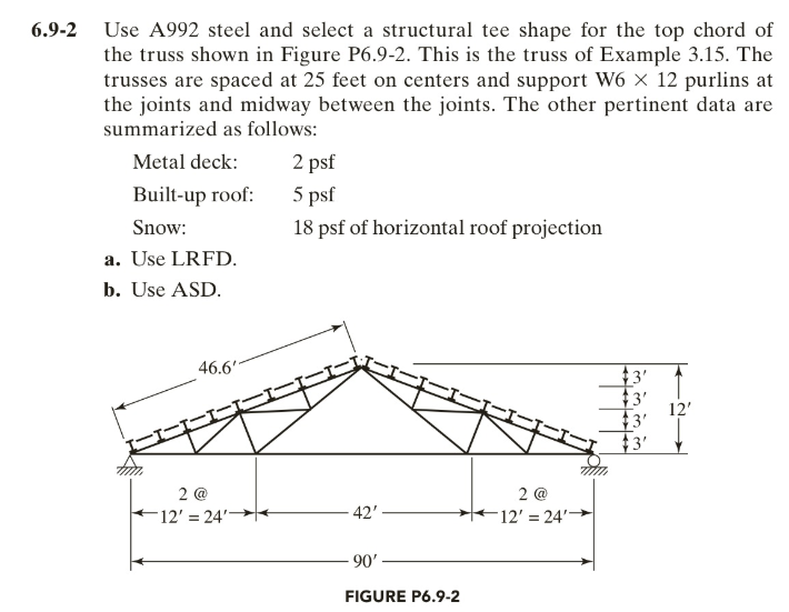
Solved 6 9 2 Use A992 Steel And Select A Structural Tee S Chegg Com
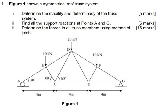
Solved 1 Figure 1 Shows A Symmetrical Roof Truss System Chegg Com
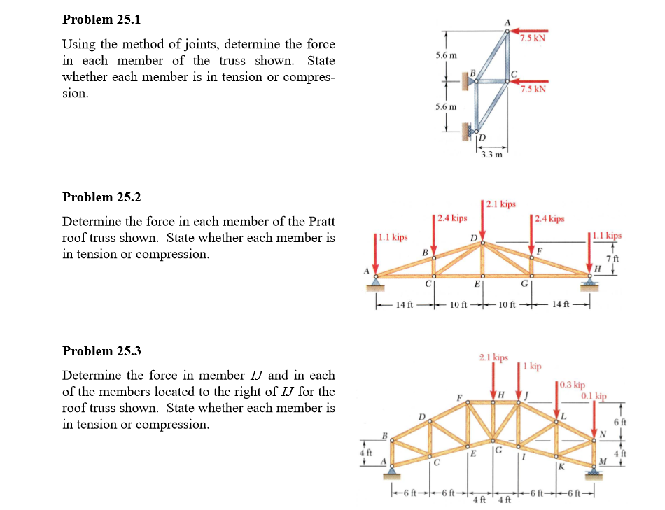
Solved Problem 25 1 Using The Method Of Joints Determine Chegg Com
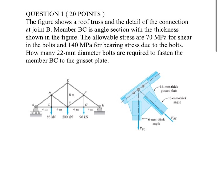
Solved Question 1 20 Points The Figure Shows A Roof Tr Chegg Com
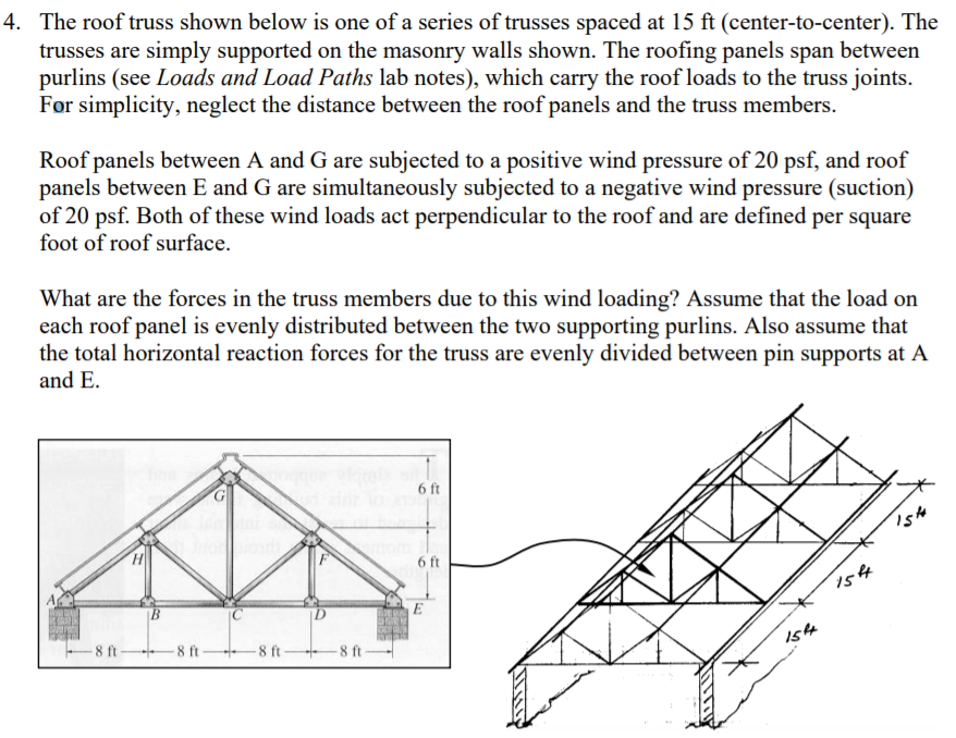
4 The Roof Truss Shown Below Is One Of A Series O Chegg Com
Solved Edit To Add I Am Not Asking For You To Find Any F Chegg Com
Solved The Roof Truss Shown Is Supported By A Pin Joint A Chegg Com
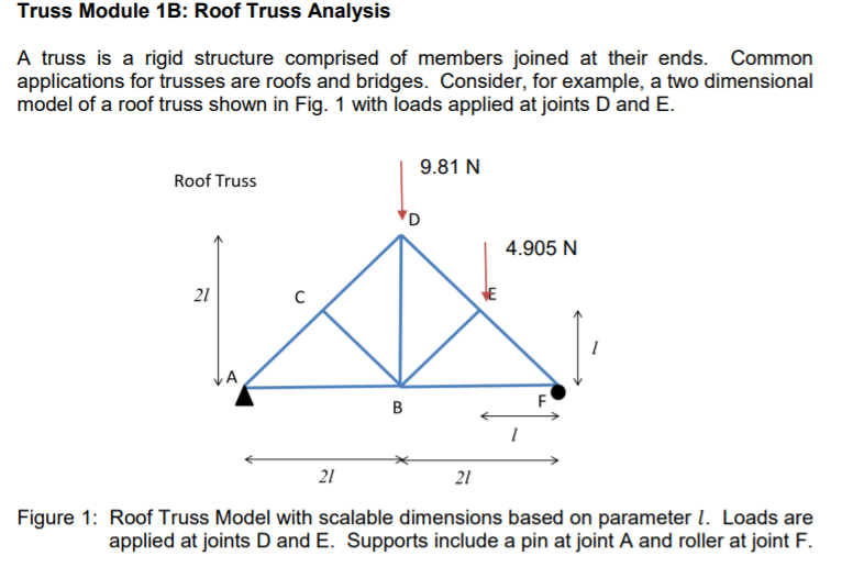
Solved Truss Module 1b Roof Truss Analysis A Truss Is A Chegg Com
Solved Using The Method Of Joints Determine The Force In Chegg Com
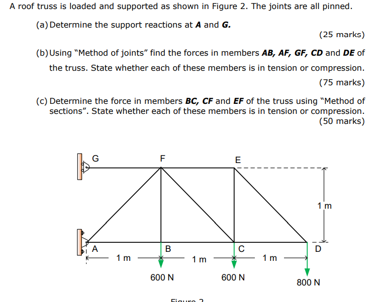
Solved A Roof Truss Is Loaded And Supported As Shown In F Chegg Com
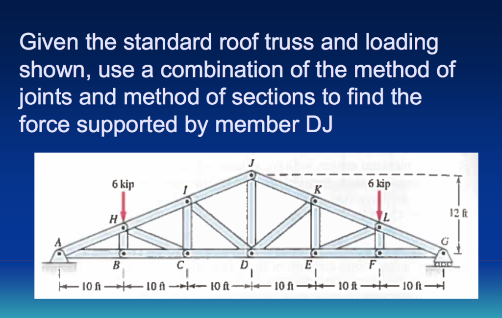
Solved Given The Standard Roof Truss And Loading Shown U Chegg Com
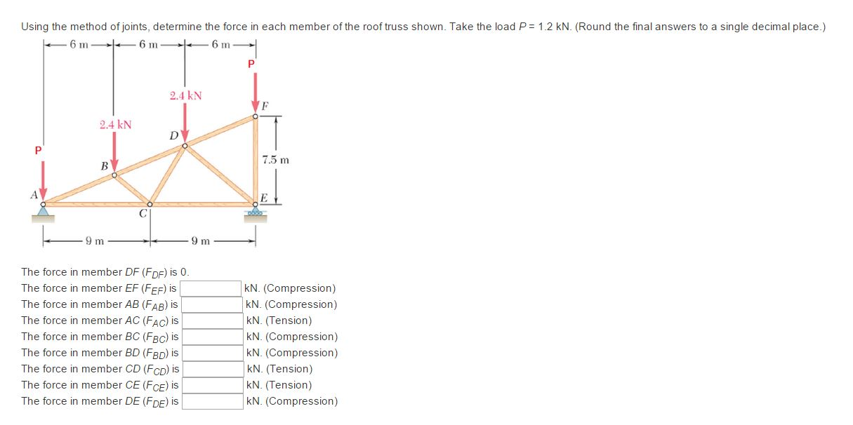
Solved Using The Method Of Joints Determine The Force In Chegg Com
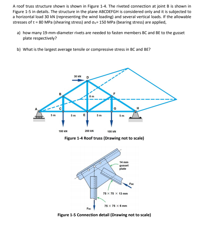
Solved A Roof Truss Structure Shown Is Shown In Figure 1 Chegg Com
Source : pinterest.com
